
The use of Finite Element Calculations in Pressure Equipment Design has now become a standard procedure either in USA or in Europe, in all cases where the traditional “Design by Formulae” is not able to provide a specific solution. Such calculations are in fact much cheaper now than they were 50 years ago, when the size and the cost of the computers which could perform them was extremely higher than the size and the cost of the modern laptops used today by the designers. This is the reason why all the main design standards are now containing specific clauses providing instructions to perform Design by Analysis as an alternative to Design by Formulae, while also the methods used in the finite element calculations have been considerably improved, going from the very simple elastic material model to the more complex elastoplastic models, which require a much higher amount of computer memory and also a change in the design approach: from the traditional approach based on the value of the stresses, to a more complex approach based on the value of the strains.
In any case there is a very basic problem affecting all people who are responsible for the certification and approval of FEM calculations: they are generally considering the simple calculations based on the formulae much more reliable than any kind of FEM calculation. It is true that the acceptance of normal calculations based on the formulae gives less doubts: if my formula tells me that the minimum thickness of a pressure vessel component is 9,99 mm, 10 mm is certainly acceptable; and I am not obliged to express an opinion about the category of a stress found in a FEM analysis, or on the kind of constraint given by a foundation bolt: in other words, I am not obliged to act and to reason as an engineer: in fact, to say that a figure is smaller or higher than another figure requires a much smaller amount of engineering judgement. It is true that sometimes also the interpretation of the formulae contained in the calculation standards may give raise to doubts: for example, what is the diameter of a nozzle? Its geometrical diameter? Or the geometrical diameter plus two times the corrosion allowance? Or, maybe, plus two times the sum of the corrosion allowance and the design tolerance? Well, in DBF also the solution of such Solomonic doubts is not particularly complicate: just take the most conservative case, and you will be sure that nobody will be able to object.
This is the reason why all the engineers, whose main task is to approve or disapprove a FEM calculation, are always in search of the support given by some prescription which is reasonable only when the calculation is made by formulae, thus ignoring the fact that a FEM calculation is made just in the case that the formulae are not applicable, either for the particular geometrical shape of the component, or in the case that we need a better picture of the stress (and strain) situation in a particular location of the same component. In fact, in part 3 of the Unfired Pressure Vessel standard EN13445 it is clearly stated that “methods based on Design by Analysis may be used to supplement or replace Design by Formulae”. I remember a terrific discussion with an engineer of a reputed research institution to whom we had presented the FEM analysis of a weld detail designed for a particular tube to shell connection: he assured us that a design by analysis of this detail is only possible for the weld details contained in the list of acceptable details provided by Annex A of the standard (Design requirements of pressure bearing welds): funny, considering that we had decided to perform a FEM analysis just because our connection did not respect the dimensional limitations imposed by any one of these details. We tried to argue that in part 4 of the same standard it is clearly stated that “…it is not intended that these (details) are considered mandatory or should restrict development of welding technology anyway, and as a result other suitable weld details may be used”; but even this sentence was not enough for him. Another comment, always related to the FEM calculation we had performed, was the idea that all the stresses (primary, secondary, local or general) should have been corrected with a joint efficiency, and since our weld detail concerned a weld not fully penetrated, in his opinion the value of the joint efficiency should be 0,7, that is the minimum possible value: thus ignoring the fact that Annex C (Design by Analysis based on stress categories), never prescribes a correction of the stresses using joint efficiencies, except for the case of general primary membrane stresses in the governing welds of cylinders, spheres and cones, just in order to avoid a possible reduction of the minimum thickness required for such components below the minimum values obtained by the relevant calculation formulae.
At the end, the key point of the discussion is the following: when we perform a design by analysis, to which extent this design is replacing the geometrical constraints given by the standard? If we carefully read the sentences of EN 13445.3 and EN 13445.4, in my opinion the analysis doesn’t replace only the formulae, but also the geometrical constraints, which have been imposed just to define the limits within which the same formulae are valid. Therefore, to say that Annex A of EN 13445.3 is a “normative” annex, doesn’t mean that the solutions provided in this annex are the only allowable solutions, and that any other solution would mean a non-compliance with the standard; it simply means that the information given for each one of the weld details described in the annex (concerning its use in specific testing groups, in corrosive environments, etc.) must be considered.
Note that the same philosophy is shared by the most advanced American Pressure Vessel standard ASME Section VIII division 2, which has two separate clauses concerning design: section 4 contains calculations by formulae, and section 5 calculations by analysis. Section 4 contains also the more usual weld details; however, in the case of nozzle to shell connections, the relevant tables are organized in the same way as Annex A of EN 13445, except for the title of the tables, that starts always with “Some acceptable welded nozzle attachments…”: it is clear the intention to give, from one side, the necessary prescriptions and limitations pertaining to the most usual cases when a DBF is performed, but, on the other side, not to limit the possibility of using alternative solutions: these details are in fact not repeated in Section 5, because the prescriptions given in this section are valid either for the weld details of Section 4, or for any possible alternative solution: in both cases the validity of the calculation is not based on the formulae, but on a FEM analysis.
And now let’s see which are the cases in which a FEM analysis based on Annex C of EN 13445.3 (that, is based on a fully elastic model and prescribing different allowable stresses for the different stress categories) may be questionable. First of all, we have to note that the main advantage of using the approach of Annex C is the fact that the superposition of different loads is very easy, since the stresses are always proportional to the loads, whatever is their value: no problem if the resulting stress will go beyond the elastic limit, the stress categorization will provide a suitable solution: secondary stresses (or better, variation of secondary stresses) may be allowable up to two times the elastic limit, no limit for peak stresses (except for the number of cycles in fatigue applications). The only problem is that the behaviour of metallic materials is normally different: particularly carbon and low alloy steels do not support stresses beyond the elastic limit: so when in your analysis you find stresses above this limit, this simply means that these stresses do not exist: what really exists is the local strain in the areas where we are accustomed to say that there is a stress concentration, that we should really call a strain concentration. For ductile materials, like steels, generally there is no problem when this happens locally in relatively small areas: however we should not forget that also in this case local stresses might mask the formation of a plastic hinge, that is an area where there is a displacement of a component in respect of the adjoining one, displacement not detected by the analysis, which however could modify also the distribution of primary stresses, and therefore the stability of the vessel. A typical example is the rotation at the periphery of a circular flat end welded to a cylindrical shell: when the local secondary stresses at its periphery reach the yield point on the entire shell thickness, this will cause the formation of a plastic hinge: which means that, above a definite pressure load, the behaviour of the end switches from fixed to simply supported, with a substantial increase of the primary bending stress at its centre.
Another case in which even normal FEM programs are not giving reliable results, is the case of compressive stresses distributed on wide portions of a component: in this case the failure mode that has to be expected is not the gross plastic deformation or the creep (usually controlled by limiting the general primary stress to an allowable value based on the yield point, the tensile strength or the creep properties); and not even the ratcheting (deterioration of the crystal lattice usually controlled by limiting the maximum range of secondary stresses to two times the yield point): the failure mode is the instability of static equilibrium (buckling) that doesn’t depend on the value of the stress, but simply on the elastic modulus and on the slenderness of the structure; the typical case is the one of the beam, whose resistance under compressive load is higher when it is thick and short, and lower when it is thin and long. To examine this case using a normal FEM program looking simply at equivalent stress intensities (that are always positive figures) will lead to the wrong conclusion that a tensile load on the beam will have the same consequences as a compressive load. In fact, such cases must be examined using more complex software programs, based on the deformed shape of the structure.
Well, it is clear that FEM calculations should be performed and discussed by engineers with a solid background in Pressure Vessel design and Analysis: even if, for some specific features, as the so called “meshing” of a structure, the man hours of young people accustomed to play with video games may be cheaper than the man hours of experienced engineers, who are more familiar with pen and paper than with computer monitor, mouse and keyboard: unfortunately, despite of the effort made by software writers, to convert the drawing of a solid pressure vessel component into a drawing of the same component made by hundreds of small solid bricks, still requires a considerable number of man hours. And, as all the design and calculation activities on pressure equipment, reduction of the number and the cost of these man hours is important in order to reduce the final cost of the product.
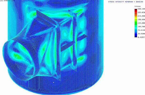
In any case, it has to be recognized that design reports made by FEM calculations are definitely more attractive than design reports based on formulae: the coloured pictures showing the level of stress in every part of the structure, as the pictures showing the deformations (maybe enhanced by 10 or 100 times) are really artistic products, with the further advantage of suggesting a presumption of correctness which is certainly unusual in the normal design reports. However, dealing with their correctness, never forget that checking FEM calculations is also something that can hardly be performed, unless you are able not only to see the report with the nice pictures, but also to get a file containing the original mesh, so that it is possible to check this file maybe with the same FEM program, or even with an alternative one, thus obtaining the same results of the original report: which certainly would greatly increase the cost of the certification activity (maybe this is the reason why some engineers responsible for the design approval are sometimes finding excuses to reject FEM calculations claiming non conformity with the relevant harmonized standards). But it is a fact that the Pressure Equipment Directive explicitly permits design by analysis as an alternative to design by formulae, exactly in the cases for which there are no formulae, or the available formulae are not applicable. And all the harmonized standards dealing with pressure equipment contain specific clauses giving the criteria to be followed for such calculations.
At the end, it must be recognized that design reports needed for the construction of pressure vessels are today much more complicate than they were 50 years ago, either in the case of DBF or in the case of DBA. As a consequence, even qualified manufacturers have dismantled their design departments and are usually subcontracting design activity to specialized engineering companies. For obvious personal reasons I cannot say that I am against this situation. However, I must recognize that training of young engineers is much better possible when they work in strict contact with a manufacturing shop, where they have the possibility of touching with eyes and hands what they have seen only on the drawings, or on the screen of their laptops.
Fernando Lidonnici
Convenor of WG53/CEN TC54
Milano, May 30th, 2024
 Azienda certificata ISO 9001
© 2025 Sant'Ambrogio Servizi Industriali // Piazza Carlo Donegani 8, I-20133 Milano // Tel. +39 02.70603113 // VAT: 09221480156 // credits

