Clause UHX of ASME Section VIII division 1 defines the rules for the calculation of tubesheets in shell and tube heat exchangers. This calculation is based on the Gardner’s theory (1948-1952), also considered in Appendix A of the TEMA standards (previously generally used in tubesheet calculations): however Clause UHX of ASME VIII division 1 also contains a series of additions and improvements which make this standard far more complicate than TEMA, and in many cases requires information and data not known by the mechanical designer.
The Gardner’s theory takes into consideration the bending and shear stresses caused by shell side and tube side pressures on the tubesheets, and also the axial stresses in the tube bundle caused by the tubesheet deflections. Of course the problem is relevant in the cases where two tubesheets are connected together by a tube bundle, that is in floating head and fixed tubesheet exchangers. In these exchangers the reaction of the tube bundle against the tubesheet deflections is the one of an elastic foundation, which will take a portion of the pressure loads, depending on the mutual elasticity of the components: thin and flexible tubesheets will transfer a substantial part of the pressure loads to the tube bundle as axial tensile or compressive tube stresses, while thick and rigid tubesheets will take themselves the greater portion of the pressure loads as tubesheet bending and/or shear stresses.
The calculation rules are far more complicated in fixed tubesheet heat exchangers (TEMA types BxM, AxL, NxN), where also the stresses due to the differential thermal expansion between shell and tubes shall be considered, and where also the shell is called to give a contribution to the tubesheet stability: in these exchangers the effect of the differential thermal expansion is converted into an additional tube side pressure when the tubes are colder than the shell, or into an additional shell side pressure in the opposite case. Also the stresses resulting from the Poisson’s effect in the shell and in the tubes are considered: in fact hoop stresses caused by pressure in these components have an effect similar to the temperature difference between shell and tubes, since they will also cause longitudinal expansion/contraction, with consequent additional loads acting on the tubesheets.
It has to be noted that since the UHX and the TEMA standards are based on the Gardner’s method, in both standards a high tubesheet thickness may be needed just to reduce local tensile or compressive stresses is some part of the tube bundle (which has very low allowable compressive stresses, imposed by the need to prevent tube buckling). In such cases the mechanical designer has no possibility to change the characteristics of the bundle (tube dimensions and baffle spacing: tube buckling stress is smaller when the free tube length between two baffles is large), because these data have been fixed by the thermal designer: therefore the only possibility to avoid an increase of the tubesheet thickness it often the adoption of an expansion bellows on the shell. Moreover, in the cases where the differential expansion of the tubes in respect of the shell is large, even very high tubesheet thicknesses cannot lead to a substantial reduction of tube stresses, particularly when the tubes are under compression: in these cases the expansion bellows remains the only possible solution.
Moreover, Clause UHX contains an important addition to the Gardner’s theory: in fact in this theory the edge rotation of the tubesheet is considered only in the two extreme cases of simply supported (free rotation, no edge moment) and fixed tubesheets (no rotation, high edge moment). On the contrary, UHX takes into account more accurately the flexibility of the tubesheet border, giving correlations for the calculation of the tubesheet edge rotation resulting from the mutual rigidity of the tubesheet, the shell and the channel (in case of channels welded to the tubesheet). The effect of this rotation may become important even if the tubesheet itself is correctly dimensioned, because it may cause high bending stresses on the other components. In other words, in the UHX method the need for a high tubesheet thickness may not depend on its own stability or on the stability of the tubes (as in the TEMA standards), but also on the need to reduce high secondary bending stresses on the shell and/or the channel. In such cases, the possibility of an increase in thickness of these components has also to be carefully evaluated, since it is generally more economic than the increase of the tubesheet thickness, considering the higher costs of the material and of the drilling operation. Therefore an automatic optimization of the tubesheet thickness made by keeping constant all the other thicknesses may be misleading.
A further problem in fixed tubesheet exchangers, not considered either by the Gardner’s theory or by the TEMA standards, is the one of the thermal stresses caused by the radial thermal expansion of the tubesheet. In fact the tubesheet operating temperature may be different from the operating temperature of the rim (its peripheral undrilled portion) and from the operating temperatures of the shell and the channel (at least in cases where also the channel is welded to the tubesheet). Supposing that these four components were not connected with each other, in going from room temperature to the respective operating temperatures their diameters at the connection would become different. This virtual difference will therefore generate additional thermal stresses, which, as all the thermal stresses, are commonly categorized as secondary stresses: that is, they cannot cause a plastic collapse of any one of the components, but only a local plasticization, that can be dangerous only after a great number of temperature cycles. This happens when the range of the fictitious elastic stress during each cycle is greater than twice the elastic limit (or three times the allowable stress). This is the reason why the radial thermal expansion has to be taken into account only in the cases provided in par. UG22 e) of ASME Section VIII division1 (“cyclic and dynamic reactions due to pressure or thermal variations, or from equipment mounted on a vessel, and mechanical loadings”). According to UHX the need to take into account the radial thermal expansion must be prescribed by the user, who is also responsible for giving to the mechanical designer the “tubesheet temperature at the rim”, the “channel temperature at the tubesheet” and the “shell temperature at the tubesheet”, together with the “tubesheet operating temperature” (which is needed also for the proper calculation of the tubesheets in all cases governed by the differential thermal expansion of the tubes in respect of the shell).
As a consequence, the design of the tubesheets in fixed tubesheet exchangers shall be made as follows.
- 14 different conditions shall be considered: 3 design conditions (4 when there is vacuum either on shell side, or on tube side, or on both sides) in which only the pressure load is considered, and 4 operating conditions taking also into account the differential thermal expansion between shell and tubes (thermal expansion + shell side pressure, thermal expansion + tube side pressure, thermal expansion + both pressures, thermal expansion alone). However for all the above conditions a double calculation is needed, because the situation may be different in corroded and uncorroded conditions. The stresses to be verified are the bending and shear stress on the tubesheet, the stresses (tensile and compressive) on the tubes (including the check of the tube to tubesheet joints), the stresses (tensile and compressive) on the shell.
- In all design conditions the bending stress in the tubesheet is to be compared with a nominal design stress equal to 1,5 S, while the limit for the shear stress is to be taken equal to 0,8 S. (S = allowable stress from the tables of Section II, part D). For the channel and the shell possibly connected to the tubesheet, that are loaded by its edge rotation, the limit is the usual limit of all “secondary” stresses (that is, those stresses that are not necessary for the equilibrium, but are caused by the mutual restraint of the adjoining components): for such stresses the limit stress range shall be 3S. If this limit is exceeded, it is possible (only for the design conditions) an additional verification using the so called “plasticity correction factor”. This additional verification is not possible in the 4 operating conditions, and the only possibility to reduce the secondary stresses remains the increase in thickness of some one of the adjoining components (shell, channel or tubesheet). As said above, the increase of the tubesheet thickness could be more economically avoided through the increase in thickness of other components, for example the channel and/or the shell.
- In case of very high compressive stresses in the tubes, due to the already mentioned impossibility to increase the buckling stress provided by the standard by changing either the tube dimensions or the baffle pitch, it is often necessary to increase the tubesheet thickness just to reduce the compressive stress in the tubes. Of course there are situations where the buckling stress in the tubes is exceeded whatever is the tubesheet thickness: and there are also cases (for example with very high shell side pressures) where there is not even the possibility of inserting an expansion bellows in the shell. In all these cases the possibility of using a different heat exchanger type should be taken into consideration.
- Note that one of the fundamental problems in carrying out a fixed tubesheet calculation in accordance with UHX is the determination of the average shell temperature and of the average tube temperature. These data are generally available in the thermal design specification, which must show at least the inlet and outlet temperatures of the tube side and the shell side fluids. However, while it is reasonable to suppose that the average shell temperature may be obtained as the average between the inlet and outlet temperature of the shell side fluid, the determination of the average tube temperature, if it is not explicitly reported in the thermal specification , is far more complicate: in fact the tubes are in contact with both the tube side and the shell side fluids, and their average temperature (which, by the way, is not the same in each tube side pass) depends on the average film coefficients of both sides: in other words, the tube temperature is closer to the temperature of the fluid which has the higher film coefficient. If these data are not available, it is very difficult, except in a few cases, even to give a rough estimation of such coefficients. Just to make a few examples, when it is sure that one of the coefficient is substantially higher than the other one, it may be assumed that the tube temperature is the average of the side with the higher coefficient: in a heat exchanger where steam at 150°C is condensing on the shell side, while in the tube side there is a gas or a very viscous liquid heated from 50 to 100°C, the tube temperature is close to the shell temperature, so you may assume that both the shell and the tubes are at 150°C (in a case like this it could be wise, in order to provide a minimum thermal expansion, to suppose that the film coefficient on the tube side is at least 10% of the one of the shell side: in which case, considering that the average temperature of the tube side fluid is 75°C, the resulting temperature difference of 125°C with the shell side fluid would cause a decrease of the tube temperature of 12,5°C, so that an average tube temperature of 150 – 12,5 = 137,5°C may be considered). Of course if you reverse the fluids you get a shell temperature of 75°C, while the tube temperature can be conservatively left at 150°C. Note that even when the thermal specification provides the values of the shell and tube temperatures, it must be clarified how the exchanger is put into or out of service: in this situation, taking the second example, one must be sure that the shell side fluid is progressively heated by the tube side steam at 150°C, otherwise there is the risk of having the tubes at 150°C while the shell is still cold, therefore with a differential thermal expansion certainly higher than in operation.
- One more problem (and this is generally never solved even in presence of a detailed thermal design) is the determination of the tubesheet temperature: in all operating cases it is possible to consider the nominal design stresses at this temperature, which is of course lower than the design temperature. Basically, the tubesheet is in contact more with the tube side fluid than with the shell side fluid: considering that also tubes welded to the tubesheet are generally light expanded into the tube holes, most of the heat transferred from the tube side fluid to the tubesheet flows through the inside tube surface, which is generally much higher than the tubesheet surface in contact with the channel ; this surface is certainly also higher than the tubesheet surface in contact with the shell. Moreover, the tube side film coefficient at tube inlet is generally higher than the film coefficient along the tube. Therefore in most cases it is reasonable to suppose that the operating temperature of the tubesheet is equal to the operating temperature of the tube side fluid flowing into or out of the tubesheet: which of course involves the need to consider the number of tube side passes of the exchanger. In fact a single pass exchanger must have one tubesheet at the inlet temperature of the tube side fluid, and the other tubesheet at the outlet temperature of the same fluid (which involves a double calculation), while for a multipass exchanger both tubesheets may be considered at on operating temperature equal to the average between inlet and outlet tube side temperatures. Particular attention however should be given to exchangers with very high tube side temperatures, like the so called waste heat boilers: in these cases the tubesheet temperature cannot be simply taken equal to the tube side inlet temperature, also because these tubesheets are intentionally made reasonably thin in order to decrease the heat input from the tube side fluid: a particular thermal calculation may be needed in order to find the operating tubesheet temperature of these exchangers.
- When the check of the “radial thermal expansion” of the tubesheet is required, it has to be made only in the 4 operating load cases: the relevant standard calculation procedures shall be modified by adding the consideration of the radial thermal stresses generated because of the temperature differences existing in the 4 adjoining parts: the rim (outside undrilled part of the tubesheet), the shell, the channel and the tubesheet itself. UHX makes a difference between the “operating temperature of the tubesheet” and the “tubesheet temperature at the rim”, that is, the temperature of the tubesheet at the periphery of the bundle: in reality there is no specific reason to suppose that the outer part of the drilled area is at a temperature different from the one existing inside, therefore the same value may be taken for these temperatures. It has to be noted that, in the cases where this radial thermal expansion is generating high radial tubesheet stresses, an increase of the tubesheet thickness has generally a negative effect: also in these cases automatic software procedures based on the progressive increase of tubesheet thickness may not lead to a solution, which shall be carefully investigated considering a possible change of other parameters. The starting point should be always a tubesheet thickness which has been previously assessed considering only the standard design and operating load cases, before adding the radial thermal expansion.
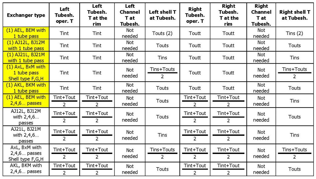
Formally the UHX calculation of a fixed tubesheet exchanger is valid only if both tubesheets have the same thickness and the same boundary conditions (that is, tubesheet operating temperature and temperatures of the adjoining components): which happens unfortunately very seldom. Therefore in all cases where the 2 tubesheets are in a different situation, a reasonable approach is the one to perform a double calculation, each one with the specific conditions of one of the tubesheets, taking then the most conservative design. This happens very often when the calculation of the radial thermal expansion is prescribed. Note that generally neither the thermal specification nor the user’s design specification contain sufficient data to find the “tubesheet temperature at the rim”, the “channel temperature at the tubesheet”, the “shell temperature at the tubesheet” and the “tubesheet operating temperature”, as required by UHX. The following tables are therefore a suggestion, in all cases where the user is not able to supply the data needed for the calculation (with Tint and Toutt, Tins and Touts we have indicated the inlet and outlet temperatures of the tube side and the shell side respectively). All the TEMA types of fixed tubesheet heat exchangers have been considered, for the case of a single tube side pass and for the one of several tube side passes (always supposing, as it usually happens, an even number of passes).
AxL and BxM exchangers (tubesheet bolted to channel and integral with shell)
NxN exchangers (tubesheet welded to shell and channel)
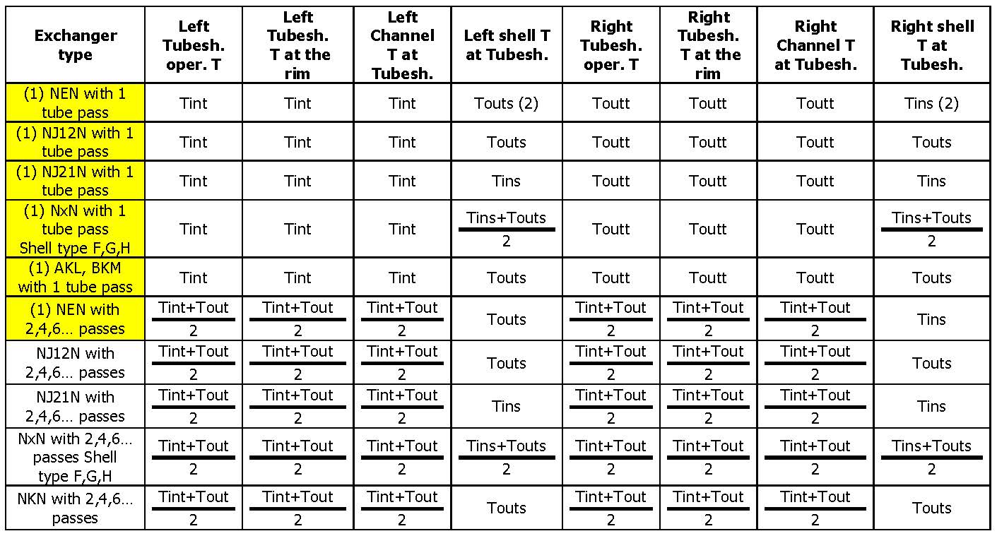
Notes:
- For these cases a double tubesheet calculation is necessary.
- Data valid for countercurrent arrangement – if concurrent reverse the two temperatures
- J12 is a TEMA type J with 1 inlet and 2 outlets, J21 is a TEMA type J with 2 inlets and one outlet.
F. Lidonnici


 Azienda certificata ISO 9001

